|
A simple
way to understand how we achieve the
separation of compounds (contained in a
sample), is detailed in the following
diagram.

First,
let’s look inside a column. In the top
cut away of a packed HPLC column, we see
the mobile phase entering the column on
the left being represented by the Green
Arrow. It passes through the column and
exits on the right. At Time Zero, (the
moment an injection is made) the Sample
Band enters the column. This “sample” is
a mixture of yellow, red and blue dyes,
which appears black in color. (In real
life, it could be anything that can be
dissolved into a solvent, and typically
the compounds would be colorless, so we
need the Detector to “see” the separated
compounds). As time passes, with a
continuous flow of mobile phase past the
packing material particles, the
individual dyes move at different
speeds. This is because there is a
competition between the Mobile Phase and
the Stationary Phase for attracting the
different compounds, also called
analytes (for our diagram, we are using
dyes). Notice that the yellow dye band
moves the fastest and is almost out of
the column. The yellow dye “likes” (is
attracted to) the mobile phase more than
the other dyes, which prefer the
stationary phase particles. Therefore,
it moves at a faster speed, closer to
that of the mobile phase. The blue dye
band “likes” the packing material the
best, much more than the mobile phase.
Therefore, it slows down significantly
because it is attracted to the
stationary particles. It is the most
“retained” compound. The red dye band
has an intermediate attraction for the
mobile phase and therefore it moves at
an intermediate speed through the
column. Since each dye band moves at
different speeds, we are able to
separate them chromatographically.
What is a
Chromatogram?
A
chromatogram is a representation of the
separation that has chemically
(chromatographically) occurred in the
HPLC system. A series of “peaks” is
drawn on a time axis. Each
peak represents a different
compound. The chromatogram is created by
the Detector and Computer Data Station.

What is a
Detector?
The
separated dye bands leave the column and
pass into the Detector. The Detector
contains a “ Flow Cell ” that “sees”
(detects) each separated compound band
as it passes through. (In real life,
most compounds in a liquid are clear and
colorless.) The Detector has the ability
to sense and signal the presence of a
compound for the Computer Data Station.
There are many different types of
detectors that can be utilized,
depending on the characteristics of the
separated compounds.
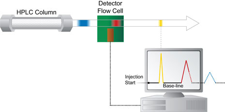
As shown in
the diagram, the yellow band has
completely passed through the flow cell,
which generates an electrical signal
that is sent to the Computer Data
Station. The resulting “chromatogram” is
starting to be shown on the screen. Note
that at Time Zero, the chromatogram
begins when the sample was first
“injected” and is represented as a
straight line at the bottom of the
screen. This is called the “Baseline”,
and represents pure mobile phase passing
through the flow cell over time. As the
yellow band passed through the flow
cell, a signal was sent to the Computer
Data Station. This causes the trace to
leave the baseline, going up and coming
back down to create the “peak”, because
the mobile phase now has a concentration
of yellow in it. After the yellow band
completely passed through the flow cell,
the signal goes back down to the
baseline, since the flow cell now has,
again, only pure mobile phase in it. The
overall shape of the yellow band is
represented as a “Peak” on the
chromatogram. Since the yellow band was
the fastest, eluting first from the
column, it is the first “peak” drawn.
After some additional time, the red band
reaches the flow cell. The signal rises
up from the baseline as the red band
first enters the cell, and the peak for
the red band begins to be drawn. In this
diagram, the red band has not fully
passed through the flow cell. The
diagram shows what the red band and red
peak would look like, if we could “Stop
Action” at this moment. Since most of
the red band has passed through the
cell, most of the peak has been drawn,
as shown with the “solid line” trace. If
we could go back to real time and
“Restart”, the red band would completely
pass through the flow cell and the red
peak would be completed (dotted line).
The blue band, which was the most
retained because it was traveling the
slowest, would have followed. The
“dotted line” trace shows you how the
completed chromatogram would have
appeared if we had let time continue.
Identifying and Quantifying Compounds
The three
separated dye compounds are represented
by three peaks separated in time in the
chromatogram. Using comparison reference
standards of compounds, a
chromatographer would be able to
identify each compound from it’s’
location in the chromatogram, based on
the “Retention
Time” (tR).
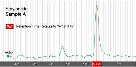
In this new example below, the compound
Acrylamide elutes at 2.85 minutes.

The next
piece of information we need to know is
“how much” of each compound was present
in the sample. The Chromatogram and the
related data from the Detector help us
calculate the concentration of each
compound. The detector basically
responds to the concentration of the
compound band as it passes through the
flow cell. The more concentrated it is,
the stronger the signal; this is seen as
a greater height response from the
baseline.

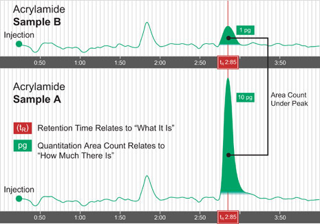
You are
looking at 2 different chromatograms on
the same page. The upper chromatogram is
from “Sample B”, and the lower from
“Sample A”. We injected the same volume
of sample in each case, but “Sample B ”
has a much smaller peak. Since the
“Retention Time”, (tR) at the apex of
both peaks is 2.85 minutes, this
indicates that they are both the same
compound, (in this example, acrylamide
(ID)). The “Area” under the peak (“ Peak
Area Count ”) indicates the
concentration of the compound. This area
value is calculated by the Computer Data
Station. Notice the area under the
“Sample A” peak is much larger. In this
example, “Sample A” has 10 times the
area of “Sample B”. Therefore, “Sample
A” has 10 times the concentration, (10
picograms) as much acrylamide as “Sample
B”, (1 picogram). Note, there is another
peak, (not identified), that comes out
at 1.8 min. in both samples. Since the
area counts for both “samples” are about
the same, it has the same concentration
in both samples.
Isocratic
and Gradient Operation
There are 2
basic types of chromatographic mobile
phase operating modes which can be used
in HPLC. The first type is called “Isocratic”.
In this mode, the mobile phase
composition remains the SAME throughout
the run.

The second
type is called “Gradient”
chromatography. This type is used for
very complex samples with many
compounds. In this mode, the mobile
phase composition is CHANGED during the
separation. As the separation proceeds,
the
elution strength of the mobile phase
is strengthened. One technique is to use
a system where there are two bottles of
solvents and two pumps. The speed of
each pump is controlled (Gradient
Controller) over time to deliver more or
less of each solvent. The two streams
are mixed (Mixer) to create the mobile
phase gradient over time. At the
beginning, the mobile phase is made up
of mostly the weaker solvent. As the
time progresses, the proportion of the
stronger solvent goes up. Another system
design uses a single pump and multiple
solvent bottles. The flow from each
bottle is controlled by a gradient
proportioning valve which creates the
desired solvent strength.
 |